Selection from the original 11- page TOSHIBA datasheet 1989. ( No guaranty, result of automatic text recognition ).

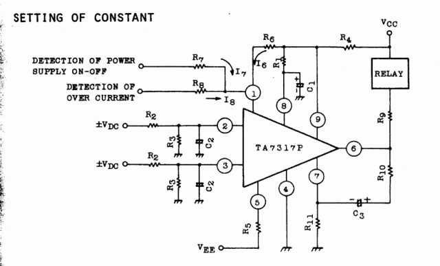
1. Setting of R1 and C1
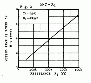
The muting time (MT) at the time when the power supply is turned on, is determined by the time constants of R1 and C1. When V8 has become about l.3V, the relay is turned ON. However, since the discharge circuit connected to pin 7 at the instant the power supply has been turned ON, there is some difference between the actual value and the theoretical value.
Fig.2 shows the measured value of R1 to the muting time (MT) in case of C1=22uF.

2. Setting of R2, R3 and C2
The R2, R3 and C2 not only determine the level sensitivity (time) detecting the DC voltage, but also operate as a filter bypassing an AC signal. The time constant of this filter is
T=C2 R2 R3 / (R2+R3) ;
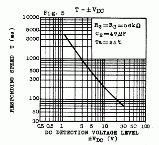
therefore, let the lowest frequency of the desired amplifier be fL, this time constant should be selected to fL>>1/2 pi T . And, the DC detecting voltage is so set that relay is ON when the absolute value of pin2- voltage (or pin3- voltage) is increased more than about 0.6 V to 0.8 V ; accordingly, the level should be set so that VDC R3 / (R2+R3) > 0.6 V to 0.8 V
As an example, Fig.5 shows the DC voltage detecting level correspending sensitivity (with the relay ON).

3. Setting of R4 and R5
R4 is a resistance to determine a current flowing into Pin 9. The current value should be set so as to become 2 ~ 3 mA .V9 is 3.l V fixed.
R5 determines a current to (pull) draw from the substrate so that the current become 3mA. It is used under the condition that V5= -0.75V because V5 is the value in the forward voltage of Q20.
4. Setting of R6, R7 and R8
R6 and R7 can determine the power supply ON or OFF, and R8 can determine the over current. R6 should be so designed that the current approx. 50 uA fully driving Q8 can be flown.
Since V9 = 3.l V and V1 = 0.75V, 47 kOhm should be used for R6.
The currents flowing to R6, R7 and R8 be I6, I7 and I8 respectively. The current relation at time of the detection of power supply ON and OFF is as follows: The current flowing in Pin 1 is considered as a positive current: I1 = I6 + I7 + I8 . R7 is connected to a negative rectified voltage, see application circuit in the datasheet. Therefore I7 ~ 0 at Power OFF. At Power ON - I7> I6 ; For example, when detection is made from AC 19Vrms, if I7 is 260uA, l00 kOhm is used for R7.
Similarly, at time of load detection, the current relation is as follows: I6 + I8 > -I7 . Compared I8 with I6 and I7, it is a larger current; therefore, R8 functions a protector for detection circuit input. Here, 47 kOhm is used for R8.
5. Setting of R9
R9 determines the current to flow to the relay. Vcc minus the saturation voltage of Q13 , V6 = Vce(sat) = 1V and the relay current and resistance cause R9.
6. Setting of R10 , R11 and C3
R10 and C3 are a resistance and a capacitor which function to allow the discharge circuit to operate instantly. The time constants of them should be extremely short. Here, R10 = 56 kOhm and C3 = 0.47 uF are used. R11 is a resistance for preventing mis-operating of dischage circuit, in which R11 = 33 kOhm.
7. Response time of output transistor
The response time of output transistor (relay driver) is designed so as to operate more quickly and more stably by means of Schmitt circuit; in case of OFF—> ON, the response time is approx. 0.5 us , while, in case of ON—> OFF, the respons time is approx. 0.2 us
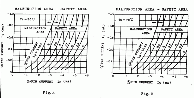
8. Setting of the current I1, I5, I9.
The value of the current I1 , I5 , I9 should be set by following relation to prevent miss operation of the relay action.
1. Set the I9 ( > 1.5 mA ).
2. I1, I5 should be set in the safety area determined by I9. The safety area is the right side area of the bound line I9 (Fig.A, Fig.B, see below ) .For improvement of the stablility against ambient temperature, the point fixed by the relation of I1 I5 should be apart from bound line to the right side.

Bemerkungen zum IC in deutscher Sprache
Achtung! Dies sind nicht die Originaldatenblätter der Hersteller, sondern Zusammenfassungen, Übersetzungen, Vereinfachungen und Erklärungen, also Interpretationen ohne Garantie für Richtigkeit. Dies ist bei der Verwendung zu beachten! Wer die Informationen beruflich braucht, sollte sich eine Kopie der Datenblätter bestellen.
Homepage index / zurück zur Startseite
Stand 30.03.03